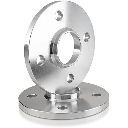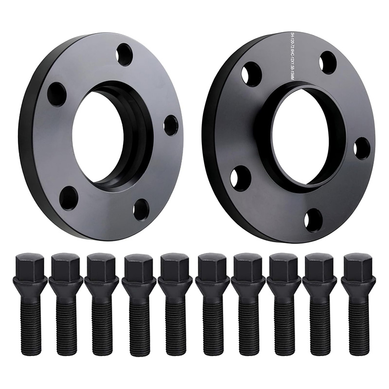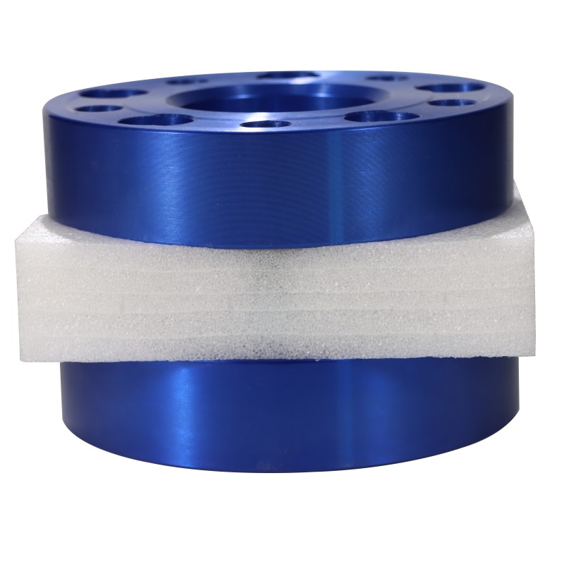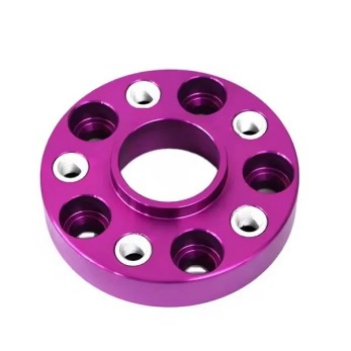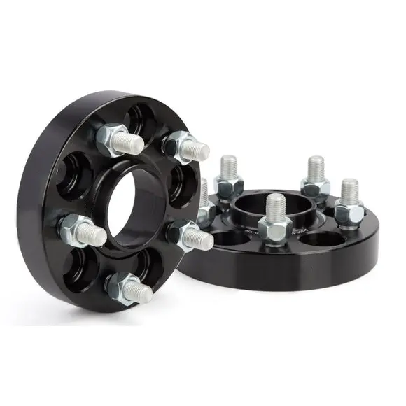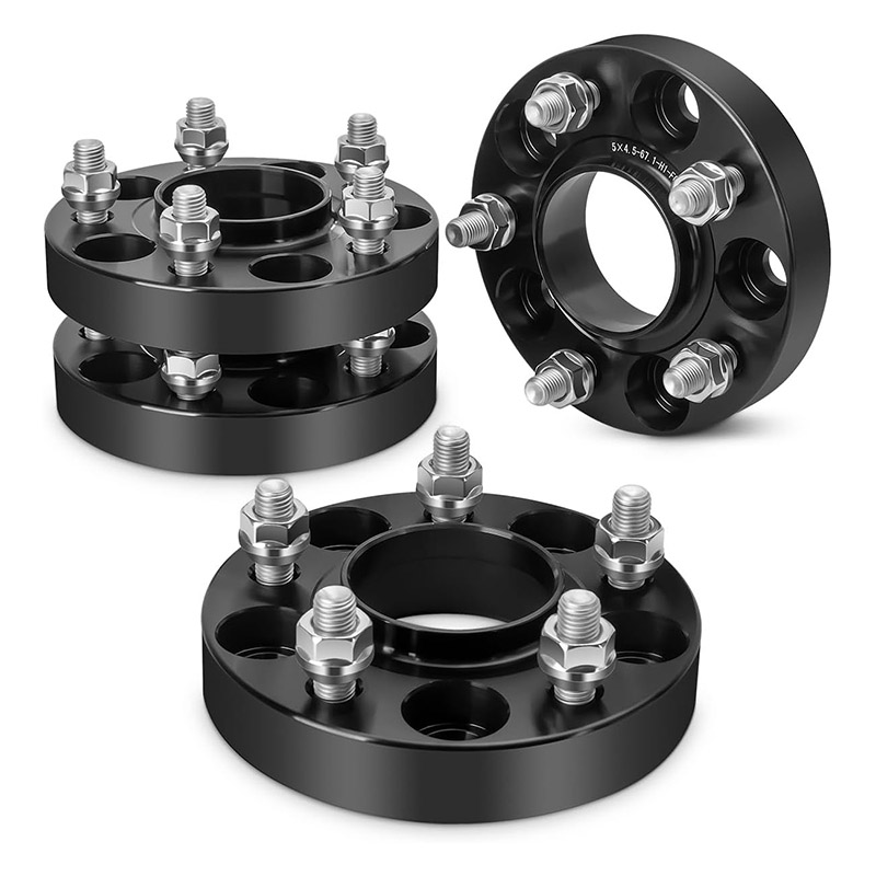
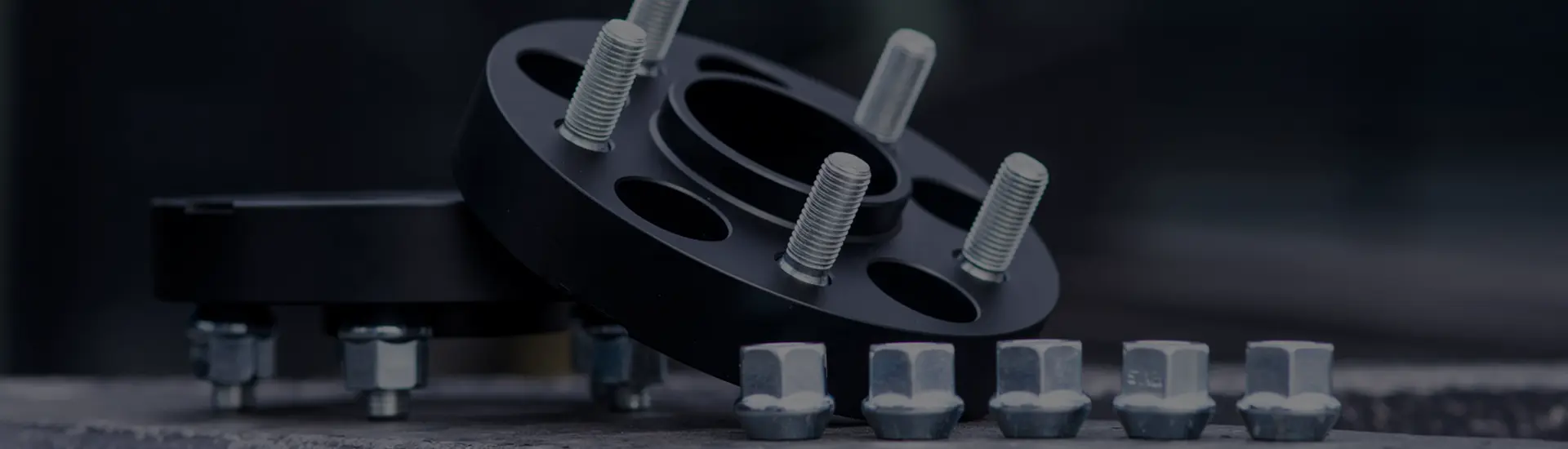

A spacer changes the distance between the wheel seat and the hub thread. The replacement hardware has to restore usable reach without bottoming, using the wrong seat or colliding behind the mounting face.

First identify which fastener path the wheel spacer uses
“Longer bolts for spacers” is correct for some systems and wrong for others. The fastener path has to be identified before any length is calculated.
The bolt passes through the wheel and spacer before entering a threaded hub. Spacer thickness reduces the original reach unless a longer bolt replaces it.
The wheel and spacer slide over studs fixed in the hub. A longer press-in stud may be needed to restore usable projection and nut engagement.
The spacer fastens to the original hub first. The wheel then attaches to a second stud set installed in the spacer.
The spacer fastens to the hub and supplies threaded wheel-side holes. Each stage has its own thread depth and fastener length.
The slip-on versus bolt-on wheel spacer guide compares the systems as complete assemblies. This page stays with the hardware dimensions inside those assemblies.
Calculate from the seating datum, not total fastener height
For a slip-on spacer that retains the same wheel and seat geometry, the first comparison is the usable length from the fastener seat to the end of the threaded portion. Decorative caps, hex heads and seat shapes are not part of that threaded reach.
H&R's TRAK+ application note tells buyers of its DR systems to choose new wheel bolts longer than the original bolts by the spacer width and to keep the bolt-head shape identical. [1] Eibach's System 6 instructions apply the same length relationship to replacement studs, while also requiring the new stud's knurl and thread dimensions to match the intended hub. [2]
This relationship belongs to those hardware paths. It is not permission to add spacer thickness to any bolt found in a catalogue. Recheck the seat, thread, hub depth and wheel geometry before approving a part number.
Example: if an approved slip-on system uses an original 27 mm usable shank and a 10 mm spacer, the starting target is 37 mm. A “37 mm bolt” is still unapproved until its stated length datum, seat profile, thread and tip clearance match the application.
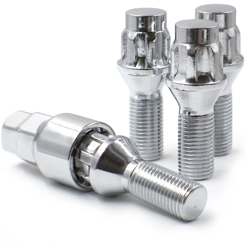
Wheel-bolt catalogues do not always describe length the same way. A conical-seat bolt is normally compared from the seating surface, not the top of the hex. A ball-seat bolt needs its own defined datum. Measure the existing hardware and read the supplier drawing rather than comparing overall silhouettes.
Thread turns and engaged length answer different questions
Counting turns is a convenient installation check. Engaged length is the axial distance over which full threads carry load. Thread pitch connects the two, but partial entry threads and bottoming can make a casual turn count misleading.
full turns × pitch
For a 1.5 mm pitch, one complete turn advances the fastener by 1.5 mm in an ideal matching thread.
Use the calculation as a check, not a universal rule
Eibach's System 6 table lists 6.5 revolutions and about 10 mm of support length for M12×1.5. The same table lists 7.5 revolutions and about 11 mm for M14×1.5. The document gives the vehicle workshop manual priority if requirements conflict.
The figures apply to that Eibach system. They show why “six turns fits every wheel” is not a responsible shortcut.
Count complete load-bearing turns after the correct seat reaches the wheel. Do not count the first wobbling partial turn as if it were a full thread. A nut that reaches its internal end can feel tight without clamping the wheel, while a long bolt can reach the bottom of a blind hub thread before the seat contacts the wheel.
| Observation | What it may mean | Measurement to make |
|---|---|---|
| Correct seat contacts, but approved turns are not reached | The bolt or stud has insufficient usable reach after adding the spacer | Seat-to-tip length, spacer thickness and actual full turns |
| Closed nut becomes tight before its seat clamps | The stud may be bottoming inside the nut | Stud projection, nut internal depth and seat contact |
| Wheel bolt becomes tight with a visible face gap | The bolt may be bottoming in a blind thread, or another interface is obstructed | Available hub thread depth, bolt projection and both mounting faces |
| One fastener reaches a different turn count | Cross-threading, dirt, damage, a seat mismatch or unequal hole depth is possible | Threads, holes, seats and fastener part numbers at that position |
| Torque rises before the seat is stable | Friction or interference may be creating a false endpoint | Stop and inspect thread condition, coatings, seat contact and bottoming |
The separate wheel spacer torque guide explains how a verified fastener stack is tightened. Torque cannot compensate for insufficient thread engagement, the wrong seat or a bolt resting on the bottom of a hole.
Longer hardware can also be too long
Increasing length restores reach through a slip-on spacer, but excess length creates another set of failure modes. The check must continue past the first engaged thread.
| System | Where excess length can go | What must remain clear |
|---|---|---|
| Wheel bolt into threaded hub | Beyond the usable female thread or through the rear of the flange | Blind-hole bottom, brake parts, parking-brake components, sensor rings and wiring |
| Stud with open nut | Through the open end of the nut | Socket access, caps and any specified maximum projection |
| Stud with closed nut | Into the closed internal cavity | Enough internal depth for the stud before the nut seat clamps |
| Bolt-on spacer on original studs | Past the spacer's outboard mounting face | Wheel back-pad pockets or approved recessed hardware geometry |
| Press-in replacement stud | Behind the hub flange and outward through the nut | Stud head, brake assembly, knurl seat, wheel and nut depth |
Eibach's System 6 instructions call for one complete hand rotation after installation and require the work to be checked again if there is contact with axle, ABS or brake components. Use the procedure for the exact installed system.
Do not shorten a bolt or stud simply because the exposed tip looks long. A qualified workshop first determines where the seat clamps, how much full thread remains, which component creates the interference and whether the relevant manufacturers permit a different part or modification.
Thread size alone does not specify wheel spacer hardware
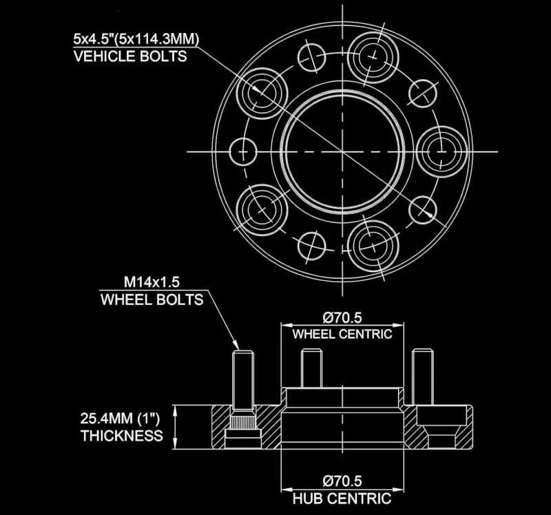
M14×1.5 describes a nominal thread diameter and pitch. It does not identify the seat, usable length, hex, tip, strength requirement, coating, nut depth or press-in geometry. The wheel and spacer drawing need the rest of the fields.
Record the seat before measuring length
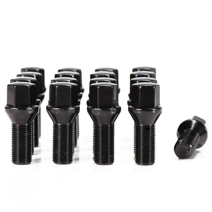
The seat is the datum where clamping begins. A 60-degree conical seat, a ball seat and a flat seat contact the wheel differently. Their overall lengths cannot be compared from the top of the head.
J&W lists both M14×1.5 conical-seat wheel bolts and other seat types in its wheel lug bolt range. Select by the complete wheel and spacer interface.
Press-in studs need hub-side dimensions
A replacement stud is not approved by thread size and shaft length alone. Eibach's System 6 instructions specifically require the knurl diameter and knurl length to correspond to the original stud. The head, shoulder and space behind the hub flange also need to fit. Pressing a stud into the wrong bore can damage the hub or fail to retain the stud correctly.
Stud replacement calls for the vehicle workshop procedure, suitable tools and a trained technician. The article does not publish a generic knurl interference or pressing force because those values belong to the actual hub and stud design.
A bolt-on wheel spacer can hide a pocket-depth problem
On some bolt-on designs, the original vehicle studs or their retaining hardware remain proud of the spacer's outboard face. The wheel back pad needs pockets in the correct positions, with enough usable diameter and depth, or the wheel will stop before its mounting face reaches the spacer.
Measure projection after the spacer is seated with its approved hub-side hardware. Then map each projecting feature against the wheel. A deep pocket that is off-center does not help. Nor does a pocket that clears the stud tip but contacts the original nut or fastener head around it.
If the wheel has no suitable pockets, use an approved spacer and wheel combination that seats flat. Do not use the wheel nuts to pull the wheel across an obstruction. The mounting face must reach the spacer without a visible gap or rocking.
Build a fastener worksheet before choosing the part number
Photograph the original fastener beside a scale, but do not quote from the photograph alone. Record dimensions from defined datums and state which side of the wheel spacer they belong to.
- Name the attachment system. State slip-on with bolts, slip-on with replacement studs, bolt-on with studs, or bolt-on with threaded holes.
- Identify both mating parts. Record the exact vehicle, axle, hub and wheel part number. Note aftermarket hubs, brakes or wheels.
- Record thread and seat. Include diameter, pitch, conical or ball profile, radius or angle where specified, and whether the nut is open or closed.
- Measure original usable length. Use the correct seat datum. For a stud, record projection, threaded length, knurl dimensions, shoulder and head geometry.
- Add the spacer thickness where the system requires it. Keep front and rear records separate when spacer thickness or original hardware differs.
- Verify engagement against the controlling instructions. Count full turns and compare the engaged length with the exact vehicle, wheel and spacer requirements.
- Check the far end. Confirm hub thread depth, nut internal depth, component clearance, stud-head clearance and free rotation.
- Check bolt-on projection against the wheel. Measure each wheel-pocket position, diameter and depth before accepting a flat dry fit.
Useful enquiry package: one photo of the hub, one photo of the wheel back pad, the original fastener beside a scale, a dimensioned sketch, spacer type and thickness, full thread and seat specification, measured engagement, pocket depth and the vehicle and wheel references.
Use the broader wheel spacer fitment guide to add PCD, center bore, lip and clearance data. Hardware approval is one part of the complete wheel-to-hub stack.
Wheel spacer stud and bolt questions
Do wheel spacers need longer studs or bolts?
Slip-on wheel spacers usually require application-specific longer wheel bolts or longer studs because the spacer consumes part of the original fastener reach. A bolt-on spacer has separate hub-side and wheel-side hardware. Follow the instructions for the exact spacer, vehicle and wheel.
How many turns should a lug nut have with a wheel spacer?
There is no universal number for every thread and vehicle. Required turns vary with thread diameter, pitch and the approved system. Count only full load-bearing turns and use the vehicle workshop manual or the exact spacer and wheel instructions.
How much longer should wheel bolts be for a slip-on spacer?
For systems that use this method, the new usable shank length is commonly the original usable shank length plus the spacer thickness. The thread, pitch and seat must remain correct, and the bolt must not bottom in the hub or contact internal components.
Can wheel bolts be too long after installing a spacer?
Yes. A bolt can bottom in a blind threaded hole or project into brake, parking-brake or sensor components before its seat clamps the wheel. Verify available thread depth and rotate the assembly by hand according to the exact product instructions.
Does a bolt-on wheel spacer use the original wheel hardware?
It depends on the spacer design. The spacer may attach to the hub with supplied nuts or bolts, while the wheel mounts to new studs or threaded holes in the spacer. Treat the two fastening interfaces as separate specifications.
Can I cut the original studs to clear a bolt-on spacer?
Do not treat cutting as a general fitment method. Use a spacer and wheel combination that provides the required clearance, or follow an explicit application-specific procedure from the relevant manufacturers and a qualified workshop.